To effectively utilize interrupts on an ARM-based microcontroller, it is important to understand the underlying hardware and software mechanisms that support them. We will first start looking at the hardware implemented in the ARM Cortex-M core used to support interrupts.
NVIC
At the heart of ARM’s interrupt system lies the Nested Vectored Interrupt Controller (NVIC), a dedicated hardware module integrated into ARM Cortex-M processors. The NVIC is responsible for managing the prioritization and handling of multiple interrupt sources, enabling efficient execution of time-critical tasks. The NVIC is entirely implemented in digital logic, functioning much like a finite state machine. This means it operates independently of software, using deterministic hardware states to monitor, prioritize, and respond to interrupt signals with minimal latency.
The NVIC supports a set of input signals, each driven by one of the microcontroller’s peripheral devices. When a peripheral detects that an interrupt condition has occurred—such as a timer expiring or data arriving on a communication interface—it asserts its dedicated interrupt signal to the NVIC. The NVIC continuously monitors all interrupt inputs and determines which interrupt is active based on these signals. Because each peripheral is connected to a unique input line, the NVIC can directly identify the source of the interrupt. In the ARM architecture, these interrupt inputs are referred to by exception numbers, which serve as unique identifiers for each interrupt source.
Interrupt Vector Table
When a peripheral asserts an interrupt, the Nested Vectored Interrupt Controller (NVIC) detects the signal and begins the process of identifying the appropriate response without any intervention from software.
The first step in this process is calculating an offset based on the interrupt’s exception number. This offset is determined by multiplying the exception number by 4, since each entry in the vector table occupies 4 bytes. The vector table is a reserved section of memory in the microcontroller’s memory map, where each entry contains the address of an ISR. Thus, the exception number effectively serves as an index into this table.
To locate the correct ISR, the NVIC adds the calculated offset to the value stored in the Vector Table Offset Register (VTOR), which holds the base address of the vector table. The resulting address points to the memory location containing the ISR for the active interrupt. The processor then fetches this address and begins executing the ISR.
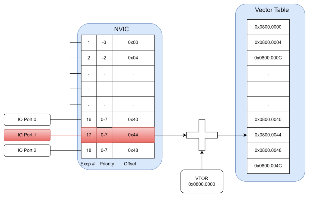
Because each peripheral is assigned a unique exception number, the NVIC ensures that every interrupt source has a dedicated entry in the vector table. For example, if IO Port 1 is assigned exception number 17, the NVIC calculates an offset of 0x44 (17 × 4) and adds it to the VTOR base address. The value at this computed address is the entry point for the IO Port 1 ISR.
Vector Table Offset Register (VTOR)
The Vector Table Offset Register (VTOR) holds the base address of the interrupt vector table. When the microcontroller is initially powered on, the VTOR is typically initialized to point to a location in FLASH memory—the read-only section of the memory map where the compiled program image is stored. This ensures that the processor can correctly locate the addresses of all defined interrupt service routines (ISRs) during startup.
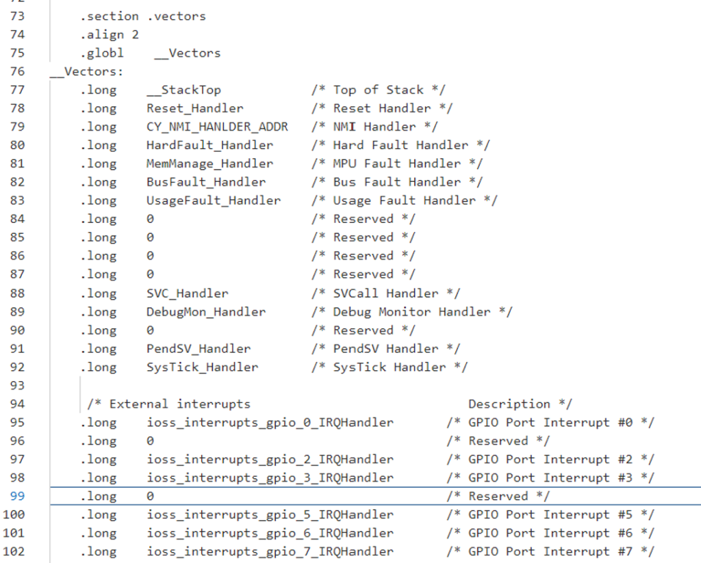
Most board support packages (BSPs) include a startup assembly file that defines the names of the ISRs for each peripheral device. These names are mapped to specific exception numbers and placed in the vector table. To define the behavior of an ISR, the firmware developer must implement a C function with the exact same name as specified in the assembly file. During the linking process, the linker resolves these names and fills in the correct addresses in the FLASH-based vector table.
This mechanism ensures that when an interrupt occurs, the NVIC can use the exception number to calculate the correct offset, access the vector table in FLASH, and retrieve the address of the corresponding ISR—all without any runtime configuration. This tight integration between hardware and software allows for efficient and deterministic interrupt handling.
While the Vector Table Offset Register (VTOR) is typically initialized to point to FLASH memory at startup, it can also be modified to relocate the interrupt vector table to SRAM. This change can only be made in a privileged CPU mode, ensuring that non-privileged code cannot accidentally—or maliciously—redirect interrupt handling to unauthorized routines.
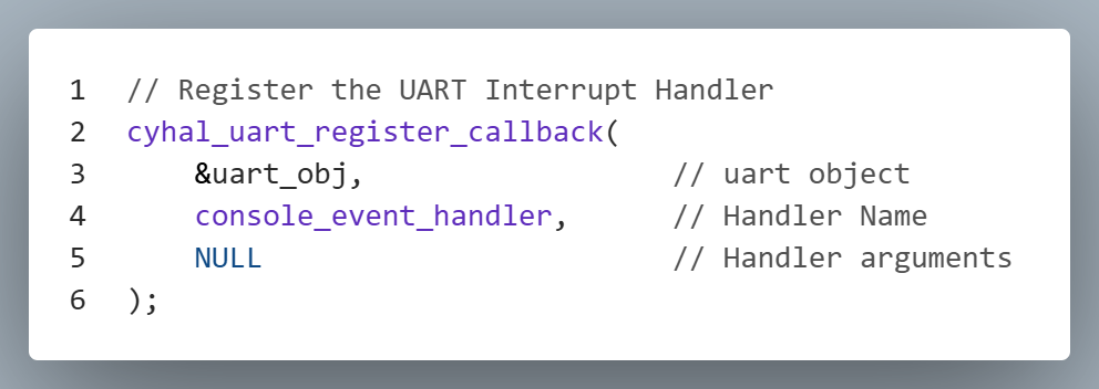
So why would we want to move the vector table to SRAM? The key advantage is runtime flexibility. Unlike FLASH, which is read-only during normal operation, SRAM is writable, allowing software to dynamically modify the vector table entries. This enables the system to register callback functions at runtime as active interrupt service routines (ISRs). For systems that support multiple operational modes, this capability allows the behavior of an ISR to change depending on the current mode. By updating the vector table in SRAM, the system can seamlessly switch between different ISR implementations for the same interrupt source.
Executing ISR
Understanding how the NVIC determines which interrupt service routine (ISR) to execute is only part of the story. When an interrupt occurs, the currently running application code must be temporarily halted, the ISR must be executed, and then the application must resume exactly where it left off. This transition is known as a context switch, and it is a critical part of interrupt handling.
The context of an application is defined by the contents of the processor’s 16 general-purpose registers, along with key status registers such as the program counter (PC), stack pointer (SP), and processor status register (xPSR). These registers hold the current execution state, including the address of the next instruction, temporary data, and control flags.
To perform a context switch, the NVIC automatically takes a snapshot of these registers and saves them to the interrupt stack. This snapshot preserves the exact state of the application at the moment the interrupt occurred. Once the context is saved, the NVIC loads the program counter with the address of the ISR, fetched from the vector table. This begins execution of the ISR without any software intervention.
After the ISR completes, the NVIC restores the saved register values from the stack, effectively resuming the original application as if the interrupt had never occurred. This seamless transition is entirely managed by the NVIC and the ARM core’s exception handling mechanism.
A key takeaway from this process is that interrupts are asynchronous to the application code. The NVIC handles detection, context switching, ISR execution, and restoration automatically, without any explicit calls from the application. In fact, application code should never directly invoke an ISR.
Enabling Interrupts
In order for an interrupt service routine (ISR) to be executed, some initialization code must be written to enable the interrupt both in the peripheral module and in the NVIC. This setup typically occurs during the system’s initialization phase—after the microcontroller is powered on but before the application enters its normal operational state. Without this configuration, the NVIC will not recognize or respond to interrupt signals from the peripheral.
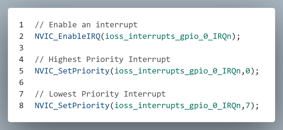
During this initialization phase, the programmer also has the ability to assign a priority level to each interrupt. This priority determines which ISR is executed first if multiple interrupts occur simultaneously. In ARM architecture, lower numerical values represent higher priorities. For example, an interrupt with priority level 0 will preempt one with priority level 2.
This prioritization system allows for nested interrupts, where a higher-priority interrupt can interrupt an ISR that is currently executing. In such cases, the NVIC performs another context switch—just as it would when interrupting normal application code—saving the current ISR’s state before executing the higher-priority ISR. Once the higher-priority ISR completes, the NVIC restores the previous ISR’s context and resumes its execution.
If an interrupt occurs with the same or lower priority than the currently executing ISR, it will be deferred until the current ISR finishes. This ensures that only one ISR of a given or lower priority runs at a time, maintaining system stability and predictability.
The code below provides an example of how to enable an interrupt and set its priority level.
ARM Cortex-M Interrupt Priority
Most embedded systems will have multiple interrupts active. So what happens when the ISR of one peripheral device is being executed and another interrupt occurs? The answer to that depends on the priority of each ISR. The ARM architecture allows us to set different priority levels for different interrupts. The lower the interrupt number, the higher priority. If an ISR is already running and a higher priority interrupt occurs, the lower priority ISR is interrupted and the higher priority ISR begins to execute. When the higher priority ISR finishes, the remainder of the lower ISR will then complete.

If the second interrupt is of the same priority or lower priority, the active ISR will complete and then the second interrupt’s ISR is executed. Notice that the second ISR is not executed immediately, but it does in fact get executed.

If multiple lower/same priority interrupts occur while a higher priority ISR is active, only one of the interrupts from the lower/same priority source will be acknowledged. The ISR status registers do not keep track of how many times a specific interrupt has occurred.
