Let’s start our discussion of pulse width modulation with some of the motivations of using pulse width modulation. Pulse Width Modulation is a technique used to control the average power delivered to a load by rapidly switching a signal on and off. It is commonly used to control the speed of motors, brightness of LEDs, and other applications where variable power delivery is desired.
A PWM signal is typically represented as a square wave that has a fixed period. In each period, the signal alternates between the “on” state and the “off” state.
The period is defined by how much time is required for the signal to repeat itself. In this screen capture, the signal repeats itself every 10ms.
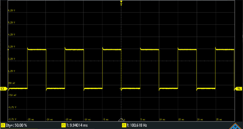
The duty cycle is defined as the ratio of the “on” time to the total period. It is usually expressed as a percentage. For example, a 50% duty cycle means the signal is “on” for half the time and “off” for the other half.
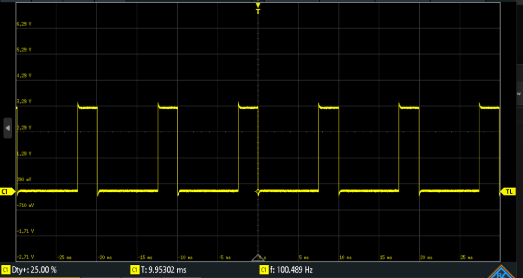
In the next image, the signal is on for 2.5ms of the 10mS period, so it has a duty cycle of 25%.
By varying the duty cycle of the PWM signal, the average power delivered to the load can be controlled. When the duty cycle is increased, the average power increases.
Smaller PWM periods generally result in smoother control. The choice of PWM frequency depends on the specific application. For example, lower frequencies may be suitable for controlling motors, while higher frequencies may be preferred for dimming LEDs.
Example Application of PWM
We will examine how PWM signals relate to the visual effect known as persistence of vision. This phenomenon refers to the way the human brain continues to perceive an image for a brief moment after it has disappeared. It allows us to experience a continuous visual scene even when the actual visual input is intermittent.
Persistence of vision is the basis for many visual effects and optical illusions. For example, a film is essentially a sequence of still images displayed at a high frame rate. As these frames are projected onto a screen in rapid succession, the brain retains each image momentarily, creating the illusion of smooth, continuous motion.
Another example is the operation of modern displays such as televisions and computer monitors. These devices refresh the screen at high enough rates to take advantage of persistence of vision, making the content appear seamless and flicker-free to the human eye.
An RGB LED contains three individual LEDs—red, green, and blue—housed in a single package. To control the brightness of each color channel, a separate PWM signal is applied to each LED. The duty cycle of each PWM signal determines the brightness of the corresponding color:
- A higher duty cycle results in a brighter color.
- A lower duty cycle results in a dimmer color.
By adjusting the duty cycle of each channel independently, a wide range of colors can be produced through additive color mixing.
The choice of PWM frequency depends on the application. Higher frequencies generally result in smoother control and reduce visible flickering. For most visual applications, a PWM frequency above 30 Hz is sufficient to prevent the human eye from detecting the on-off switching of the LED.
This image demonstrates how three I/O pins can be used to control an RGB LED.
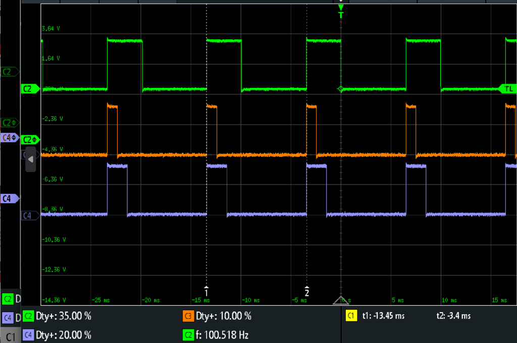
Each of the PWM signals has the same period of 10 ms, corresponding to a frequency of 100 Hz. However, the duty cycle of each signal can be varied independently to control the brightness of the red, green, and blue channels.
By adjusting the duty cycle for each color channel based on the desired output color, a wide range of colors and dynamic lighting effects can be achieved using a single RGB LED. This technique allows for smooth transitions and precise color mixing through additive color blending
Using a Timer to Generate a PWM Signal
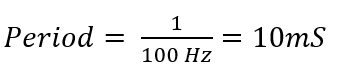
We will use a timer to generate a PWM signal to control the RGB LED. The first step is to determine the period of the PWM signal. To avoid visible flickering, we need to choose a PWM frequency of at least 30 Hz. For ease of calculation, we will use a frequency of 100 Hz, which corresponds to a period of 10 milliseconds. We will assume the MCU runs at 100MHz.
With a PWM period of 10 ms, we want the LED to be on for 5 ms and off for 5 ms to achieve a 50% duty cycle.
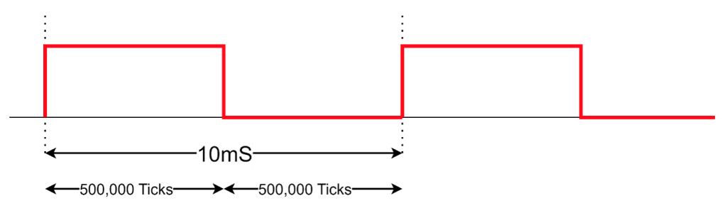
Given a microcontroller clock frequency of 100 MHz, we can calculate the number of clock cycles needed to represent the full 10 ms period.
Ticks = 5mS ×100 MHz=500,000
Therefore, the timer should be programmed to count 500,000 clock cycles for each PWM period.
The following pseudocode outlines how to generate a PWM signal with a 50% duty cycle and a 100 Hz period using software and a timer:
- Set the I/O pin to logic high (1) to turn the LED on.
- Start the timer and wait for it to expire.
- Once the timer reaches zero, set the I/O pin to logic low (0) to turn the LED off.
- Restart the timer
- Repeat this process continuously for as long as PWM signal generation is required.
Using a PWM Peripheral
While it is certainly possible to generate a PWM signal using a timer peripheral and software, most microcontrollers provide dedicated PWM hardware peripherals specifically designed for this task. The key advantage of using a PWM peripheral is that it eliminates the need for continuous CPU involvement. Instead of polling timer status bits and manually toggling I/O pins in software, the CPU simply configures the PWM peripheral with the desired period and duty cycle.
Once configured, the PWM peripheral operates autonomously, generating the signal with no additional computation overhead. This frees up the CPU to perform other tasks, improving overall system efficiency.