Configuring a UART interface for polled operation is a fairly straightforward process. However, polling a UART to transmit and receive data is very inefficient. For example, consider a UART configured with a baud rate of 115200 and an 8N1 frame format. Each byte transmission requires 10 symbols—1 start bit, 8 data bits, and 1 stop bit. At 115200 baud, this translates to a maximum throughput of 11,520 bytes per second. Therefore, transmitting a single byte takes approximately 86 microseconds.
Eighty-six microseconds may not seem like much, but on a microprocessor running at 100MHz, that translates to roughly 8,600 clock cycles per byte. That’s a significant number of cycles to spend busy-waiting to send the next byte in a sequence. To make better use of the microcontroller’s computational resources, we’ll explore hardware and software techniques that allow the CPU to perform other tasks while UART is processing data.
Interrupts
One of the most effective ways to minimize CPU associated with the UART is to enable UART interrupts. With interrupt-driven communication, the UART notifies the processor only when data is ready to be transmitted or received. This allows the main application to continue executing other tasks, making better use of the microcontroller’s computational resources.
Most UART peripherals support two general categories of interrupts: receive and transmit interrupts. We’ll begin by examining receive interrupts. A UART generates a receive interrupt when new data arrives in the hardware receive buffer. This event triggers the Nested Vectored Interrupt Controller (NVIC) to perform a context switch and then transfers control to the UART interrupt service routine (ISR). When new data arrives, the ISR typically stores the received byte(s) into SRAM for deferred processing, notifies the main application (often via a flag or message queue), and then clears the interrupt to prepare for the next event.
In most applications, receive interrupts are enabled during initialization and remain active throughout normal operation. This allows the main application to continue executing non-UART-related activities until the UART hardware signals that new data has arrived, helping to improve efficiency.
Transmit interrupts behave a bit differently from receive interrupts. Most microcontrollers generate a transmit interrupt when the UART’s transmit register becomes empty. This interrupt signals that the application can now send the next byte of data. However, if the application is not actively transmitting data, the UART may continuously generate transmit-empty interrupts. This can lead to excessive ISR executions and potentially starving the main application of processing time.
To avoid unnecessary transmit empty interrupts, the UART interrupt handler disables its own transmit empty interrupt when there is no data to transmit. This ensures that the ISR is not repeatedly triggered when there is no data to send. When the application has new data to transmit, it buffers the data in SRAM and then re-enables the transmit-empty interrupt. This approach ensures that interrupts are only generated when necessary, allowing the processor to focus on other tasks when no transmission is pending.
Hardware FIFOs
In some situations, interrupts alone are not sufficient to eliminate wasted clock cycles. A common example is printing a long string of bytes. While the first byte can be sent immediately by writing to the UART transmit register, each subsequent byte must wait until the UART is ready—typically indicated by a transmit-empty interrupt. Although interrupts help determine when it’s safe to send the next byte, they don’t change the fact that the application remains busy until the entire string has been transmitted. This can limit the application’s ability to perform other tasks during lengthy transmissions.
One effective way to reduce the time spent waiting to send or receive bytes is by utilizing a UART with a hardware FIFO. UARTs equipped with a FIFO allow the application to write multiple bytes to the transmit register at once. The UART then queues and transmits each byte sequentially until the FIFO is empty. This eliminates the need to wait for each individual byte to be transmitted before sending the next. Instead, the application can send a block of data and immediately resume other tasks, significantly improving throughput.
Using a UART FIFO also helps reduce the number of interrupts generated during data transmission and reception. With FIFO support, transmit and receive interrupts occur only after a block of data has been processed, rather than for each individual byte. Since each interrupt triggers a context switch and execution of the ISR, minimizing the number of interrupts directly reduces the number of clock cycles spent handling UART events.
One special consideration when using UART FIFOs is how receive interrupts are triggered. In many UART implementations, a receive interrupt is generated only when the receive FIFO is full—or nearly full—based on a configurable threshold. But what happens when only a single byte is received and the FIFO hasn’t reached the interrupt threshold? In such cases, we want to avoid a scenario where data sits idle in the FIFO, waiting indefinitely for more bytes to arrive. To address this, most UARTs include a receive timeout interrupt. This interrupt is triggered after a short period of inactivity when data is present in the FIFO but hasn’t reached the configured threshold. It ensures that even partial data is processed in a timely manner.
Software Buffering
While hardware FIFOs significantly reduce waiting time, they don’t eliminate it entirely. One key limitation is that hardware FIFOs have a fixed size. If the amount of data to be transmitted exceeds the FIFO’s capacity, the application must still wait to refill the FIFO as space becomes available. Since we can’t dynamically expand the hardware FIFO, a common solution is to implement a software buffer in SRAM. This buffer stores bytes destined for the UART, allowing the application to queue large amounts of data for transmission without blocking.
Producer Consumer Model
Writing firmware to support UART communication typically involves coordinating several components: the UART hardware FIFOs, software buffers, interrupt handlers, and the main application logic. A widely used approach for managing this coordination is the producer-consumer model. In this model, UART data transmission and reception are treated as two separate producer-consumer flows.
Receive
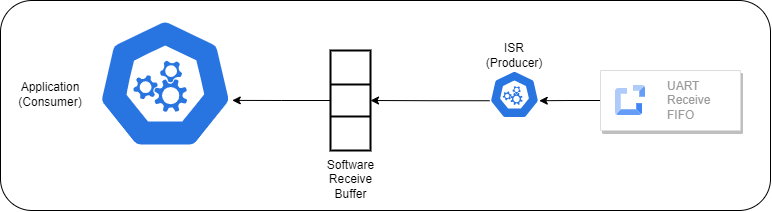
In the receive data flow, the main application acts as the consumer of the software buffer—not the UART hardware directly. Instead of reading data from the UART registers, the application monitors the receive software buffer populated by the ISR. When the buffer contains data, the application removes data for processing. If the buffer is empty, the application can choose to block and wait for new data or continue executing other tasks. This decoupling allows the application to remain responsive and efficient, processing incoming data only when it’s available.
One important design consideration when using a receive buffer is handling the case where the buffer is full and a receive interrupt occurs. This situation arises when incoming data arrives faster than the main application can consume it. Unfortunately, this always results in data loss. The key question becomes: which data should be discarded—the oldest or the newest? In practice, many implementations discard the oldest data to make room for new bytes, but there is no universally correct answer. The best solution is to prevent this scenario altogether by implementing flow control. Flow control mechanisms can signal the sender to pause transmission when the buffer is nearing capacity, helping to preserve data integrity.
Transmit
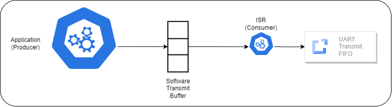
In the transmit data flow, the main application acts as the producer by inserting bytes into the transmit software buffer. When a transmit-empty interrupt occurs, the UART interrupt service routine (ISR) acts as the consumer. It removes data from the transmit software buffer and writes it to the UART transmit register, initiating transmission. This separation allows the application to queue data for transmission without blocking, while the ISR ensures that the UART hardware is kept busy transmitting data as long as the buffer contains data.
When transmitting data, the application places all outgoing data into the software transmit buffer. Each time new data is added, the transmit-empty interrupt is re-enabled to ensure the UART begins processing the software buffer. When the UART’s transmit register becomes empty, it triggers a transmit-empty interrupt. The UART ISR then checks the software transmit buffer and consumes data—transferring data into the hardware transmit register—until either the register is full or the buffer is empty.
This process continues, with the UART generating interrupts as long as there is data to send. Once the ISR detects that the software transmit buffer is empty, it disables the transmit-empty interrupt to prevent unnecessary ISR executions. As discussed earlier, the transmit-empty interrupt should remain disabled when there is no data to send. If the application adds data to the buffer while the interrupt is disabled, the UART will not be notified, and the data will remain unprocessed. Therefore, it is critical that the application re-enable the transmit-empty interrupt whenever new data is added to the buffer to ensure proper transmission.
When transmitting data using a software buffer, one important consideration is how to handle the situation when the software buffer is full. At this point, the application must decide whether to overwrite existing data or wait until space becomes available. While overwriting the oldest data is technically possible, it often leads to loss of critical information. In most cases, the preferred approach is to busy-wait until the buffer has room. Although busy-waiting is not ideal from a performance standpoint, it is generally better than losing data. This design choice ensures that all transmitted data is preserved, even if it means temporarily stalling the application.
Race Conditions
When the application modifies a software buffer—either by adding or removing data—it’s critical to ensure that these operations are atomic. Atomicity means that the entire sequence of instructions involved in the buffer modification must execute without interruption. If this is not guaranteed, a race condition can occur where the main application is modifying the buffer at the same time a UART interrupt is triggered, potentially corrupting the buffer state.
Since interrupts can only preempt lower-priority code, the UART ISR itself cannot be interrupted by the application. However, the reverse is not true—the application can be interrupted by the UART ISR while modifying the buffer. To prevent this, the simplest and most effective approach is to temporarily disable interrupts before accessing the buffer and re-enable them immediately afterward. Another approach would be to use more sophisticated synchronization mechanisms like a semaphore.